When you first begin to model processes with BPMN, it’s hard to look past the challenge of the notation itself – all the event types, flow control patterns, exception handling patterns, and the rules for sequence flows and message flows. With a bit of training and practice, the rules and diagram patterns soon become second nature, and that part of the modeling effort gets easy. But when you begin to apply that learning to capture your company’s actual end-to-end business processes, a new issue inevitably crops up: managing the complexity of the models. Real-world end-to-end models aren’t like the simple exercises you learned in class. They extend over many diagram sheets, representing deeply nested hierarchies, and may link multiple independent BPMN processes. They may include multiple references to the same task or subprocess, and for ease of maintenance and governance high-level subprocesses may be defined in separate files.
In my course Process Modeling with BPMN, offered via the BPM Institute, I previously avoided this topic, not wanting to scare off students already nervous about tackling events and exception flows. But after working with graduates of the training as they began to tackle their companies’ real processes, I came to realize you can’t avoid dealing with it. So now, in addition to the tips every process modeler should know (see Ten Tips for Effective Process Modeling), we wrap up the training with best practices for organizing these complex real-world models. Here’s a summary.
A key principle of BPM as a management discipline is understanding a business process as a single entity end-to-end, so we teach a methodology in which the entire end-to-end process is captured at very high level on a single page of the diagram. That top-level diagram includes not only a coarse-grained view of the orchestration (sequential flow) of your process, but also abstract representations of external entities interacting with your process, such as requesters, service providers, and sources of unsolicited events, and the touchpoints between your process and those entities, called choreography.
BPMN provides containers called pools to represent each such entity or process, internal or external, and all the pools involved in your end-to-end process should be drawn in the top level diagram. External entities are typically drawn as “black box” pools – empty inside, since you don’t know or control their internals. Internal pools – your own processes – are drawn as white box flows, showing the orchestration. Communication between pools is shown as dashed lines called message flows, representing all the requests, responses, and unsolicited events used to synchronize the various entities in the business process.
The purpose of the top-level diagram is not to explain how your process works, but to show how all the pieces of the end-to-end process fit together. With all the pools and message flows, there’s frankly not room on the page to provide much detail about what your internal process is doing. That detail is provided in other sheets of your diagram, each representing an expanded view of one of the subprocesses in the top-level diagram, again ideally on one page. These child-level diagrams may contain other subprocesses, which are detailed in their own child diagrams. When the end-to-end process is captured at the level of detail needed for simulation or implementation, you wind up with a deeply nested model drawn in many interlinked diagrams.
Each modeling tool has its own way of keeping the pieces together. Some leverage a built-in repository. The one we use in our course normally maintains them as separate sheets in a single Visio file. Each sheet represents what the tool calls a process level (Figure 1). (BPMN Link events allow a single process level to extend over multiple sheets, but our methodology discourages its use.) The end-to-end model can extend over many levels of nesting. A subprocess rendered collapsed – as a single activity – at a parent level can be expanded into its own process diagram at the child level. Our tool supports top-down modeling by creating and naming the child process level in one click from the collapsed subprocess. Subprocesses can also be reused multiple times within a single model by referencing, shown by the dotted line links in Figure 1.
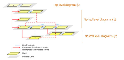
Figure 1. End-to-end BPMN models are spread out over multiple nested levels
Models fully built out in this way can extend over 10 or more sheets of a single Visio file. To manage navigation, we recommend a naming convention in which the name of the sheet is the name of the subprocess (or pool, for top-level diagrams) appended with the child nesting level in parentheses, such as (0) for top level, etc. For really complex models, you might prefer to manage some subprocesses in separate files, which allows more flexibility in maintenance.
Readability and traceability from top to bottom level are critical, including the choreography. We recommend that message flows also be shown from the top-level down to the lowest child level where they occur, which means replicating external pools and message flows in child level diagrams.
Typically your process starts with some kind of request from an external entity. It’s not necessarily a web service request, but could be a call to your call center or a piece of incoming mail. And typically it concludes with some kind of response to the requester, such as a confirmation or failure notice. Best practice is to show all those interactions in the top level diagram, even when the detailed activity that sends the response may be defined in a deeply nested child level.
That often requires propagating the success or failure indication from its source at a deeply nested level up to the top level, and then sending the response from there. BPMN lets you do that. Successful completion of a subprocess at nesting level N returns to the normal flow out of the collapsed subprocess at level N-1. Alternatively, an error end event at nesting level N sends a signal that is caught by an attached error event on the collapsed subprocess at level N-1. The exception flow out of the attached event can go to another error end event, which rethrows the exception to level N-2. Whether by successful completion of the subprocess or error throw-catch, this propagation can be repeated one level at a time until level 0, the top level is reached, from which the success or exception response to the requester is sent.
Figures 2 and 3 show how all the pieces fit together. The top-level diagram has an internal process called MyMain, drawn as a white box pool, and black box pools representing the process requester, a service provider, and another internal pool labeled MyIndependent Subprocess. The latter is drawn black box because here it’s defined in a separate Visio file. Alternatively, I could have made it white box and defined it in another top-level diagram of the main Visio file.
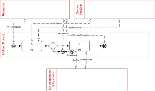
Figure 2. Top-level diagram shows all pools and choreography
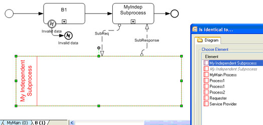
Figure 3. Exceptions at child levels should be propagated to top level to return a response
Note that the process requests and both success and failure responses come from the top-level diagram, even though one source of failure, labeled Invalid Data, originates at some deeply nested level, 2 or higher. This exception is propagated to level 1, the attached error event on B1, and from there up to level 0, the attached error event on B. At level 0, the exception flow leads to the message event that returns the response.
Note also at level 1 the choreography between the activity calling MyIndependent Subprocess and the separate pool of the same name. It’s done this way in order to manage that subprocess in a separate file. If we kept it in the same Visio file, we could just expand MyIndep Subprocess at a new process level. That’s simpler, but we lose the ability to maintain the two files independently.
Each organization needs to evolve its own conventions for managing complex models. They will depend on the tools used and the nature of the complexity. But in the end it is vital to establish such conventions and teach everyone involved in end-to-end modeling to learn and adhere to them consistently. Learning basic diagram patterns is fine as a starting point, but once you start BPMN modeling for real, managing complexity becomes the larger issue.